Synthesis of ZSM-5: A Size/Shape-Selective
Zeolite Catalyst for Xylene Isomerization
Overview
This experiment involves the synthesis and characterization
of the synthetic zeolite ZSM-5 and the study of the catalytic properties of
the material towards xylene isomerization. The ZSM-5 structure contains
two intersecting channel systems of specific size and shape that restrict molecular
diffusion into and through the framework. The porous material is therefore
useful for catalytic reactions inside the nanopores of the material. The
synthesis of ZSM-5 involves hydrothermal methods over a period of two days.
Subsequent labs will involve characterization and calcination of the material,
followed by an intrazeolite xylene isomerization reaction.
Introduction
Zeolites are crystalline, microporous three-dimensional aluminosilicates, comprised of corner-sharing TO4 tetrahedra (T = Si, Al).1-4 The general formula is Mx/n[(AlO2)x(SiO2)y]zH2O, where M is an extra-framework cation that balances the anionic charge of the framework. The oxygen atoms are doubly-bridging and connect two metal centers; the tetrahedra are arranged into n-membered rings, where n = 4 or larger. A six-membered ring, for example, contains six "T-atoms" (Si or Al) and six oxygen atoms. For simplification, the latter are ignored in this nomenclature, as well as in structural representations of zeolites, where metal centers are joined by a straight line (Figure 1).
Figure 1. The MFI topology is one example of a zeolite. The dark atoms show the space-filling view.
One example of a zeolite is ZSM-5 (Figure 1), which contains with two sets of perpendicular, intersecting channels, one defined by 10-membered rings and the other by 8-membered rings. The ZSM-5 structure is a commonly occurring framework topology, where the chemical composition of the metal centers varies. As a result, there are now over 21 different names for this structure, and the material is instead commonly referred to by its assigned three-letter zeolite structure code, MFI.4 The specific pore size and shape of zeolites, as well as their high degree of thermal and hydrolytic stability, render them useful for size/shape-selective catalysis. When the material is calcined to porosity and converted to its acid form, strong Brönsted acid sites allow catalysis of hydrocarbon isomerizations inside the nanopores of the material.2-5
Typical zeolite synthesis involves hydrothermal methods, where an aqueous mixture of sodium silicate, sodium aluminate and sodium hydroxide is heated for extended periods of time. In this lab, the sodium form of ZSM-5 will be formed after 44 hours of heating. It will then be calcined to render the material porous and subsequently converted into the active acid form for the xylene isomerization reaction.
Preparation of Zeolite ZSM-5
Lab #1
N.B.: The following preparation must be conducted in a fumehood. Solid silicic acid is a light material and is easily airborne, not unlike asbestos fibers. You must avoid breathing any small, air-suspended particles. In addition, n-propylamine is volatile and toxic.
Grind up approximately 0.55 g of NaOH pellets with a mortar and pestle. Place 0.50 g of the pre-ground NaOH in a 250 mL beaker, and add 2.01 g of silicic acid (SiO2·H2O), followed by 1.01 g of tetrapropylammonium bromide [(C3H7)4NBr]. Add 5.0 mL of distilled H2O to this and mix as thoroughly as possible with a spatula. Add 1.0 mL n-propylamine (n-C3H7NH2) with a pipet and mix thoroughly.
In a separate 50 mL beaker, prepare a solution of 0.25 g of aluminum sulfate
[Al2(SO4)3·16H2O] dissolved in 5.0 mL distilled
H2O. Then add to this solution, 0.05 mL of concentrated sulfuric acid via a micro-syringe or pipet.
Carefully transfer the contents of the first beaker to the second and mix
thoroughly. Slowly add distilled H2O to give a total volume
of approximately 25 mL, using a portion of this distilled water to rinse the solid that remains in the 250 mL beaker into the 50 mL
beaker. Finally, mix the contents of the 50 mL beaker thoroughly until the solution
is homogeneous, and then allow to stir on a magnetic stir plate for
approximately ten minutes.
Transfer the majority of this mixture to a 45 mL or
125 mL capacity Parr Stainless Steel Autoclave (the former works better...can
you guess why?). Seal the autoclave by first hand-tightening the top until
it can turn no further. If you are using a 45 mL capacity autoclave, use
the hook spanner wrench to seal the chamber by turning the top by ~ 90 degrees.
If you are using a 125 mL capacity autoclave, first hand-tighten the screws,
and then use an Allen wrench to tighten the six bolts, working your way around
the circle several times. Place in a pre-heated oven at 160°C for 44 hours.
Lab #2
Remove the autoclave from the oven and place in a stream of cold water from a tap (preferably in a fumehood) to quickly bring the synthesis mixture to room temperature. When cooled, open the autoclave and vacuum filter the white solid on a Buchner funnel. Wash the solid on the filter paper with copious amounts of distilled water and suction dry the solid for at least 20 minutes. The dried powder should be a very fine, colorless powder. Weigh the solid, and remove a small sample for powder X-ray diffraction analysis
.
Calcination and Conversion of Zeolite ZSM-5
Set up the tube furnace assembly for the calcination step by placing the zeolite in an alundum or quartz boat. Spread the white powder out to maximize the surface area. The alundum boat is placed in the middle of the quartz of alumina tube. Attach a ground glass elbow at each end of the tube, with one end attached to an N2 cylinder and the other end immersed in a beaker of water or connected to a bubbler, to monitor the N2 flow rate. If the tube furnace is not programmable: Slowly heat the tube and its contents to 500°C: water vapor will be released from the solid around 100°C. It is therefore best to heat slowly at this point. Heat in increments of 20°C until 100°C is attained, maintaining each temperature for 5 minutes. Then increase the temperature to 500°C in 100°C increments, holding 10 minutes at each temperature. If the tube furnace is programmable: heat from 20°C to 100°C in 20 minutes, at a rate of 4°C/min; then 100°C to 500°C in 40 minutes, at a rate of 10°C/min. When the assembly has finally reached 500°C, continue heating for 2 hours. Allow the materials to cool and weigh the resulting solid. Another sample is removed for X-ray analysis.
The sodium form of the zeolite is converted to the acid form using the following procedure: the calcined zeolite is placed in a 100 mL beaker and stirred with a 1.0M (NH4)2SO4 (aq) solution (10 mL/g zeolite) for 10 to 15 minutes at ambient temperature. The zeolite is collected by vacuum filtration. It is also advantageous to wash the zeolite with small amounts of acetone, to dry the solid and partially remove the brown/black color. Repeat this process twice, following the final treatment by a thorough washing with distilled water, until the filtrate is free of sulfate anions. Test the filtrate by adding an aqueous solution of BaCl2 dropwise to the contents of the filter flask. The presence of a BaSO4 precipitate will indicate that the zeolite still contains adsorbed sulfate ions; if the solution is clear, you may proceed to the next step.
Wash the zeolite one last time with a small amount of acetone (to dry it) and then dry the solid, in a small dry beaker or the alundum boat, in the 120°C oven for 30 minutes. Transfer the dried solid to the tube furnace by spreading it over a large surface area in the alundum boat. Heat the materials in air at 500°C for a period of at least 3 hours. Do not pass N2 gas over the solid - the presence of O2 is essential for the conversion. At the end of this time period, you will notice that the zeolite has lost its brownish tinge and should appear white. Cool the material under a stream of nitrogen and store in a sealed vessel in a desiccator to preserve the acid hydrogen form of the zeolite.
Powder X-ray Diffraction Analysis
Run powder X-ray diffraction spectra on your as-synthesized and calcined samples to confirm its structure, purity and crystallinity. Mix your sample with a very small amount of petroleum jelly (just enough to make a paste), and "paint" the mixture onto the center of a glass slide. See Appendices for the operation of the Miniflex X-ray Powder Diffractometer. Your material should display a pattern similar to the characteristic X-ray diffraction pattern of ZSM-5 (Figure 2, 3). A comparison includes the relative intensity of the peaks, peak width, and the 2q values (also see Appendix). Using Bragg's Law (nl = 2dsinq, where n = 1 and l = 1.5418Å for CuKa radiation),9 calculate the value of d for the most intense peak present in your experimental TPA-ZSM-5 and the reference diffraction pattern. How do the d-spacings compare?
Figure 2. As-synthesized TPA-ZSM-5 displays a characteristic
powder X-ray diffraction pattern.
Figure 3. Calcination of ZSM-5 changes the powder X-ray diffraction pattern from that of the as-synthesized material.
Catalytic Testing of ZSM-5
Lab #3
Xylene isomerization is carried out in a fumehood, using a simplified catalytic reactor (Figure 4). Place a known mass of ZSM-5 catalyst in the fritted adapter, followed by glass wool. (Do not use too much glass wool or sample or the xylene will be unable to flow!) Using vacuum grease, connect this central piece to glass tubes with ground joints, such that glass tubes are protruding from each end of the tube furnace. Heat the tube furnace to 425°C. Connect the rest of the pieces shown in Figure 4, and fill the reagent flask with 8 mL of o-xylene.
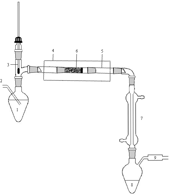
Figure 4. A catalytic reactor is used for the isomerization reaction. (1)
Heated reagent flask; (2) Nitrogen inlet; (3) Thermometer; (4) Tube furnace; (5) Catalyst
reactor tube; (6) Sintered glass frits to retain catalyst; (7) Condenser; (8) Product
collection flask; (9) Bubbler or flow meter.
Heat the o-xylene to its boiling temperature (140°C). Flow N2 gas through the hot o-xylene at a low to moderate flow rate (indicated by the bubbler) to act as a carrier gas. Place the collection flask in an ice bath, to ensure condensation of the xylenes, which should occur within 10 minutes. Cool the product mixture to ambient temperature and take a 1H NMR spectrum of both o-xylene and the product. Integrate the two peaks to determine the extend of conversion to p-xylene (Figure 5).
Figure 5. 1H NMR of the xylene mixture allows the
identification of the different isomers produced from the catalyst H-ZSM-5
(measured on a Bruker 360 MHz Spectrometer).
Also analyze the product by gas chromatography (GC). The mobile phase, or carrier gas, is an inert gas (helium). The xylene sample is volatilized at the injector, and moves through the column [8´ by 1/8", 10% OV101 as the liquid phase, Chrom-P-AW-DMGS (80/100 mesh) as the solid support]. The separation process occurs as a result of repeated sorption-desorption acts, that arise from the differences in the distribution coefficients of the individual sample components, during the movement of the sample components across the stationary phase. At the end of the column, the components should emerge at different times. They are then detected and the resulting signal is displayed on a recorder or printer. The peak area is used to determine the relative amounts of the individual components present in the sample.
The optimum conditions for the GOW MAC 550P are as
follows: injector temperature: 140°C; column temperature: 135°C; detector
temperature: 157°C; bridge current: 150 mA; gas flow: ~ 4 cc/min; attenuation:
8; sample size: 1 mL; chart speed: 10 mm/min.
1.0 mL of pure samples of o-xylenes, m-xylenes,
p-xylenes and mixtures such as 1:1:1 volumes of o-,m-, and
p-xylenes are injected into the gas chromatograph. The retention
times of these components are calculated and the peak area is determined by
cutting them out and weighing them. Is the column capable of separating
o-,m-, and p-xylenes? Keeping in mind that gas chromatography
separates components on the basis of their boiling points and polarity, are
your experimental results supported by theory?
Adsorption Analysis
Run the physisorption isotherm for the as-synthesized
and hydrogen form of your zeolite. Use the Micromeritics ASAP 2020 Analyzer
in S2-G19 with your TA or a member of the Oliver group. Print out the final
data and compare with typical data of any zeolite in the literature.
CAChe Component
Using the crystal shape option example found in the
CAChe component of your laboratory manual, construct a ZSM-5 molecular lattice.
Construct o-, m-, and p-xylenes. Drive these molecules
into the 10-membered rings of the three dimensional channels. How does
the zeolite pore size compare with the molecular diameters of the various xylenes?
What do you observe and how does it relate to the catalytic results? Keep
in mind that rates of diffusion and absorption of organic molecules is influenced
both by the size and shape of the channel system and by the location of extraframework
cations. The issue is far more complex than that provided by the CAChe
component. Alternatively, use Materials Studio on the PC's to visualize
the structure and xylenes (check with the instructor and TA).
For Your Report
This experiment was a small-scale version of a major
industrial process, as the size- and shape-selective zeolite ZSM-5 is an industrially
important catalyst. Ion-exchange has been performed to render the sodium
form of ZSM-5 (Na-ZSM-5) and subsequently the hydrogen form, H-ZSM-5.
X-ray powder diffraction spectra have been obtained on the initially synthesized
zeolite and the sodium form. Compare the experimental spectra to literature
spectra. Use the Bragg equation to calculate the d-spacing of the most
intense (100%) peak in the Na-ZSM-5 spectrum. Isomerization of o-xylene
to p-xylene was performed and analyzed by a 1H NMR assay and
gas chromatography. The zeolite and xylenes were modeled on CAChe and
the results compared to the experimental catalytic method. In your report,
propose a possible mechanism for the catalysis of o- to p-xylenes,
and be sure to support this mechanism with literature references.
References
1. Kokotailo, G. T.; Lawton, S. L.; Olson, D. H.; Meier, W. M. Nature 1978, 272, 437.
2. Barrer, R. M., Hydrothermal Chemistry of Zeolites; Academic Press: New York, 1982. Call number: QE391.Z5B37 1982
3. Breck, Donald W., Zeolite Molecular Sieves: Structure, Chemistry, and Use; New York: Wiley, 1973. Call number: TP159.M6B7
4. Szostak R., Molecular Sieves, Second Edition; Thomson Science: New York, 1998. Call number: TP159.M9S98 1998
5. Whan, D. A. Chem. Brit. 1981, 17, 532.
6. Cheetham, A. K. in Solid State Chemistry: Techniques; Cheetham, A. K. and Day, P. Eds.; Clarendon Press: Oxford, 1987, pp. 39-51.
Additional Reading
1. Newsam, J. M. Science 1986, 231, 1093-1098.
2. Davis, M. E., Lobo, R. F. Chem. Mater. 1992, 4, 756-768.
3. Zones, I. S.; Davis, M. E. Curr. Opin. in Solid State and Mat. Sci. 1996, 1, 107-117.
4. Oliver, S.; Kuperman, A.; Ozin, G. A. Angew. Chem. Int. Ed. Engl. 1998, 37, 46-62.